
Why Geometry Matters: A Guide to Building Loads & The Arch Advantage
Structural integrity isn’t just about strong materials; it’s about how a building manages energy exerted upon it by the environment from wind, snow, and seismic activity. According to ASCE 7-22 (Minimum Design Loads and Associated Criteria for Buildings and Other Structures), engineers must account for seven distinct forces to ensure a building doesn’t just stand, but lasts.
- Dead Loads: The permanent weight of the structure and fixed equipment. This can also include “collateral loads” which are items, typically on the interior, that need to be supported by the structure.
- Wind (Roof): Upward “lift” or downward pressure from airflow.
- Wind (Facade): Horizontal “push/pull” forces on flat walls or end walls.
- Snow Loads: Vertical weight from snow, ice, and meltwater. This includes both ground snow, and roof snow, which is the more important of the two, and is a percentage of the ground snow load. These sometimes need to be increased due to the building’s surroundings, like dense trees (sheltered site) or tall structures (snow drift, shadow and sliding snow) or can also be reduced if, for example the building is continuously heated.
- Live Loads: Temporary weights from living beings (like maintenance workers and animals).
- Seismic Loads: Inertial forces triggered by the ground shaking during an earthquake.
Each of these loads must be evaluated both individually and in a series of combinations to create a safe, code-compliant structure. Under the latest version of the International Building Code, we need to account for 187 distinct load combinations.
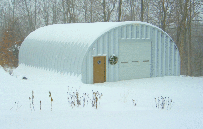
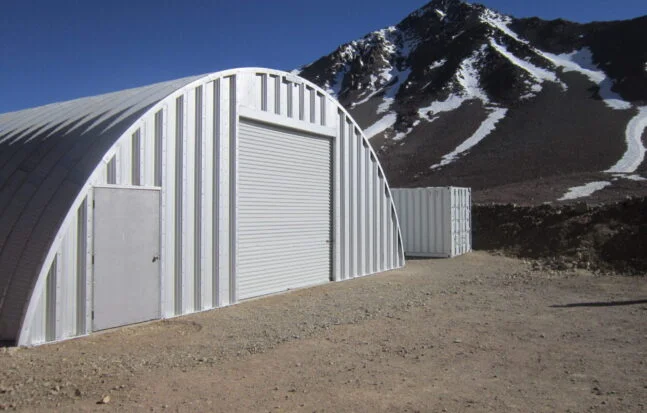
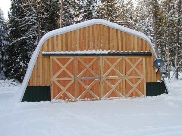
Quonset hut arches offer natural advantages in meeting these load requirements due to their curved geometry.
The continuous arch design distributes forces more uniformly than conventional rectangular structures, reducing stress concentrations and improving performance under multiple load scenarios.
The lack of sharp corners distributes the loads over larger areas instead of having them concentrated at specific points.
Load Paths & Combinations
Load paths are fundamental to structural design. Loads imposed on a building travel from their point of application down through the structural system to the foundation and ultimately into the ground. Engineers must calculate how a building’s design and materials will impact the load path and its ultimate strength.
The Load Path Concept: A building is only as strong as its weakest link. Arches offer superior load paths compared to traditional building styles
Load Combinations
Buildings are rarely subjected to a single load type in isolation. International Building Code (IBC) and ASCE 7-22 prescribe specific load combinations that account for the reduced probability of maximum loads occurring simultaneously. Common combinations include:
| Combination Scenario | Why It Matters |
|---|---|
| Dead + Wind | Ensures the building's weight is enough to keep wind suction from "uplifting" it. |
| Dead + Snow | Tests if the frame can support its own weight plus a maximum winter load. |
| Dead + Seismic + Reduced Live | Balances the structure's mass against earthquake-induced shaking. |
In total, however, our buildings need to be designed for 187 distinct combinations of loads when using the latest version of the International Building Code.
Pre-Engineered & Factory-Produced Arch Advantages In Load Paths
Engineer-designed arch systems produced in a factory provide superior performance in managing building loads:
- One continuous arch evenly distributes loads throughout the building
- Precise calculation of load paths is possible for a given application
- Optimized material usage in production
- Verification of code compliance
- Consistent fabrication conditions
- Reduced exposure to the elements during construction
- Factory quality control pre-delivery
These factors combine to produce more reliable structural performance compared to entirely field-built construction and traditional/conventional buildings. Additionally, because these buildings are purpose-built, they are designed specifically to meet or exceed your area’s minimum structural engineering requirements.
Wind Loads: Aerodynamic Design vs. Traditional Buildings
Wind creates positive pressure (pushing) on the windward side and negative pressure (suction) on the leeward side and roof. In traditional rectangular buildings, sharp corners cause “flow separation,” creating violent vortices that can strip roofing or cause “racking” (wall tilting).
ASCE 7-22 provides design wind speeds based on geographic location and Risk Category. Basic wind speeds vary significantly across regions and Risk Categories, from 85 mph to 320 mph in the United States. These are then subject to additional factors that can increase the associated pressures significantly, like exposure to large bodies of water, topography, elevation, building enclosure conditions, etc.
| Location | Wind Speed Map Figures in ASCE 7-22 | Why |
|---|---|---|
| Contiguous United States | 85-200 mph | Wind speed varies greatly based on your location, if you live in a hurricane zone, a special wind region, or a region with topographic effects |
| Alaska | 105-175 mph | Must account for seasonal snowstorms (snow drifts) and northern exposures |
| Hawaii & Territories | 100-240 mph | Must account for hurricanes and tropical storms that impact the islands |
| Puerto Rico | 140-320 mph | Due to its higher vulnerability to intense Atlantic hurricanes, which strike with more force, and topography, the average wind speed is higher |
Key Factors in Wind Load Design
- Building Height & Geometry: Wind pressure increases with height. Shape matters too — aspect ratio, roof slope, plan irregularity, and openings (like large doors) all affect how wind loads are distributed and concentrated.
- Velocity Pressure (q): Derived from wind speed: q = 0.00256 × Kz × Kzt × Kd × V² (ASCE 7). Accounts for height, topographic effects, and wind directionality.
- Pressure Coefficients (Cp / GCp): Dimensionless coefficients that quantify how pressure distributes across surfaces — windward walls, leeward walls, side walls, and roofs each have distinct values. Corners and edges experience higher local pressures.
- Directionality Factor (Kd): Reflects the reduced probability that the maximum wind speed will come from the most critical direction simultaneously with the worst structural orientation.
The Arch Advantage
- Uplift Mitigation: The gradual curve of a Quonset hut prevents abrupt flow separation. This distributes pressure evenly and significantly reduces the “suction” that often tears apart pitched roofs.
- Reduced Lateral Pressure: Without sharp corners, wind flows around the structure rather than hitting it like a sail. This reduces the “overturning moment,” which is the force trying to tip the building over.
- Exposure Categories: ASCE 7 defines three categories (B for urban, C for open, D for coastal). Because of their aerodynamic profile, arch buildings perform significantly better in Exposure D environments, where wind pressure is higher.
Snow Loads: Managing the Weight of Winter
Snow is an “environmental load” as it ebbs and peaks with snowstorms, snow melt and accumulation. Snow is a transient gravity load. While it acts vertically like a dead load, its intensity varies, requiring the structure to support massive temporary weight without permanent deformation. These loads can and often are unbalanced, adding additional and considerable complexity in design.
While ground snow load is a flat number based on location (e.g., 0 psf in Phoenix to approximately 400 psf in Lake Tahoe ), roof and wall snow loads vary because of the natural snow drift in the wind. Snow drifting occurs when wind deposits snow against vertical obstructions, creating concentrated loads that can exceed uniform snow loads by factors of 2-3.
- Thermal Factor: This accounts for how much heat the building loses through the roof.
- Heated Structures: Heat escaping the roof helps melt snow, reducing the design load.
- Unheated/Open Structures: Quonset huts used for cold storage or equipment sheds must be engineered for higher loads because snow stays frozen on the steel surface longer.
- The Winter Wind Parameter: This is a significant update in ASCE 7-22. It replaces the old “catch-all” wind maps with regional data that tracks wind patterns specifically during months with snow cover. This determines how likely snow is to blow off the roof or accumulate in dangerous drifts.
- Drift Scenarios: Even if a roof is clear, wind can deposit snow against endwalls or neighboring structures, creating “drifts” 2–3 times heavier than the uniform load. This allows engineers to calculate these concentrated “surcharge” loads with much higher precision.
- Roof Slope Factor: Steeper roofs shed snow more effectively. Arched structures benefit here because their slope increases as you move from the crown to the base, naturally encouraging snow to “slide” once it reaches a certain weight.
Arch Building Advantages for Snow Loads

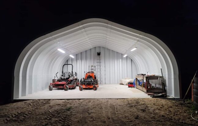
The curved profile of arch structures provides benefits for snow load management.
- Continuous curvature: Arches create a more uniform load distribution compared to the concentrated loads at valleys or roof transitions in conventional buildings.
- Steeper roofs: Models with a 4:12 pitch (model A and model X), promote snow sliding and shedding (particularly for wet or melting snow).
- No ponding instability: The continuous curve eliminates flat spots where water can pool, effectively removing the risk of roof-top ponding instability common in flat-roof commercial buildings.
The resistance against snow load forces is controlled by several factors for an arched building, including: its shape, size, the depth of its panels, the thickness and grade of its panels and, in exceptional cases, whether it has any interior supports.
The geometry of an arched building provides a natural resistance to snow accumulation and the snow-drift weight on the side of the building. Increases in steel gauge and design elements (like those seen in the model X) will further the building’s natural strength.
Seismic Performance: Strength Through Continuity
Earthquake Impact on Building Loads
Seismic loads result from horizontal ground motion during earthquakes. As the ground accelerates, the building’s mass resists this motion, due to inertia, creating internal forces throughout the structure. These forces are proportional to the building’s mass and the ground acceleration, making seismic loads fundamentally different from gravity loads like snow or dead load.
Key Factors in Earthquake Load Design
Structures are classified into Seismic Design Categories (SDC) ranging from A through F, where A represents minimal seismic risk and F represents the highest risk for critical facilities. Depending on your location’s Ground motion values, the soil type (hard rock to clay)a, and occupancy type, the SDC determines the level of seismic loads your building will need to withstand:
Seismic Design Categories (SDC) Summary:
- SDC A/B: Minimal risk, basic code provisions apply.
- SDC C/D: Moderate to High risk, requires engineered lateral systems.
- SDC E/F: Extreme risk near active faults requires maximum ductility.
Arch Advantages for Seismic Loads
The continuous curved geometry of arch structures provides several seismic performance benefits:
- Weight: Dead load is a major factor in seismic resistance. The heavier the material, the bigger the challenge that Seismic actions represent. Even when the thickest panels are used, Arch Buildings tend to be considerably lighter than traditional building materials and thus can easily handle even the highest Seismic activities in the United States and around the world.
- Rigidity/Flexibility: Rigidity/flexibility is another major factor in seismic resistance. The more rigid the material, the more susceptible it is to damage from Seismic activity. Arch Building panels are more flexible than virtually any other building material and thus can easily handle even the highest Seismic activities in the United States and around the world.
- Uniform Force Distribution: Arches spread seismic energy across their entire curve, avoiding the high-stress “joint failures” common at rectangular beam-column connections.
- Elimination of Corner Stress: By eliminating sharp corners, arches remove the vulnerable zones where twisting (torsional) forces concentrate during an earthquake.
- Inherent Racking Resistance: The arch shape naturally resists side-to-side tilting (racking) through its own geometry and compression, rather than relying on heavy, complex bracing.
- Reduced Seismic Demand from Lower Height: Their low-profile design reduces the “lever effect” of ground shaking, resulting in less total force for the structure to resist compared to taller buildings.
- High Ductility: Arch geometries can be engineered to meet Seismic Design Category (SDC) E requirements, the highest risk level for standard structures, due to their inherent ability to deform without collapsing.
Understanding the seven fundamental load types and their interactions is essential for safe structural design. Wind, snow, seismic, dead, live, earth, and load combinations must all be evaluated according to ASCE 7 provisions and local amendments. Prefabricated and arch structures offer distinct advantages through factory-controlled quality and aerodynamic geometry but must still be rigorously designed to meet all applicable load requirements for their specific location and use.